


B2F double flange type limit expansion joint
- Product Type : Retractor
- Introduction : Double flange limit expansion joint is composed of body, sealing ring, gland, telescopic short tube and other major components. On the basis of the original performance of the loose sleeve expansion joint, a limiting device is added, and the maximum expansion amount is locked with a double nut. The pipeline can freely expand and contract in the allowable expansion amount. Once it exceeds its maximum expansion amount, it will be limited to ensure the safe operation of the pipeline. It is especially suitable for the connection in the pipeline with vibration or certain inclination and turning.
Product Details
-
-
Structural features: B2F double flange type limit expansion joint is composed of flange, casing, limit bolt, sealing ring and gland. The casing is divided into two parts: the inner tube and the outer tube. The surface of the inner tube is polished, and the outer tube is thickened to enhance the pressure bearing capacity. The flange adopts symmetrical double flange design, and both ends are equipped with annular flanges, which are connected with the pipeline flange through high-strength bolts to ensure close contact at the interface. The limit bolt is located on the outside of the casing, and the expansion and contraction can be adjusted by the nut, which can not only control the maximum elongation length, but also prevent the structural deformation caused by excessive compression.
-
Material selection: The main components are made of 304 or 316L stainless steel, and the flange is processed by the overall forging process, and the yield strength reaches more than 205MPa. The sealing system adopts multi-layer combination design, with nitrile rubber main sealing ring embedded inside and polytetrafluoroethylene auxiliary sealing layer on the outside. The temperature range covers -30 ℃ to 180 ℃, and can withstand 2.5MPa working pressure. The limit bolt is made of 40Cr alloy steel, the surface is galvanized, and the tensile strength exceeds 980MPa 1.
-
Limit protection mechanism: The joint is provided with adjustable mechanical limit devices on both sides of the casing. When the axial displacement of the pipe occurs, the inner pipe slides in the outer pipe, and when the displacement reaches the preset value, the limit baffle and the stop block contact to form a physical limit, and the displacement is controlled within the design allowable range. This double protection structure can effectively avoid the casing drop-out accident caused by sudden impact, and is especially suitable for water supply systems with water hammer effect.
-
Sealing technology innovation: the use of self-tightening sealing structure, as the medium pressure increases, the sealing ring pressure to produce radial expansion, and the pipe wall to form a dynamic seal. A double sealing line is set at the flange joint surface. The first channel is a flat rubber gasket seal, and the second channel is a concave-convex labyrinth metal seal to achieve zero leakage standard. The measured data show that there is no leakage at 2.5 times the design pressure for 30 minutes.
-
Scope of application and key points of installation and maintenance: The connector is suitable for a variety of media, including sea water, fresh water, hot and cold water, drinking water, domestic sewage, crude oil, fuel oil, lubricating oil, refined oil, air, gas, and temperature not higher than 250 degrees Steam etc. During installation, it is necessary to keep the pipeline axis aligned, and the bolts shall be tightened by three times in diagonal order, and the final torque value shall be controlled at 120-150N · m. During the commissioning phase, the limit bolts shall be loosened, and the limit shall be set after the pipeline system is stable. Maintenance cycle It is recommended to check the wear of the sealing ring every 12 months
-
Main materials
|
序号 |
名称 |
数量 |
材料 |
|
1 |
本体 |
1 |
QT400-15,Q235A, ZG230-450,20 |
|
2 |
密封圈 |
1 |
NBR |
|
3 |
压盖 |
1 |
QT400-15,Q235A, ZG230-450,20 |
|
4 |
限位短管法兰 |
1 |
Q235A,20,16Mn |
|
5 |
螺母 |
4n |
Q235A,35, 1Cr18Ni9Ti |
|
6 |
长螺柱 |
n |
Q235A,20, 1Cr18Ni9Ti |
|
7 |
螺柱 |
n |
Q235A,20, 1Cr18Ni9Ti |
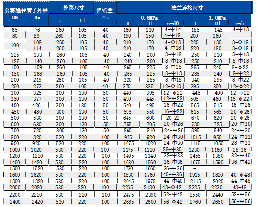
Main overall dimensions and connection dimensions (mm)
Contact Us
0371 68197888
No. 98-1, Dengfeng Road, Shangjie District, Zhengzhou City, Henan Province
Friendly Links :
Zhengzhou valve Henan Water Conservancy Mining Machinery China Resources GasButterfly valve
Double eccentric soft seal butterfly valve
Butt welding eccentric metal seal butterfly valve
Ball valve
Heating worm gear full bore welded ball valve
Heating gas fully welded fixed ball valve
Heating gas fully welded fixed ball valve
Fitting
VSSJA-2(B2F-1) double flange limit expansion joint
C2F double flange loose sleeve force transmission joint (VSSJAF)
C2F double flange loose sleeve force transmission joint (VSSJAF)
Pressure reducing valve
YX741X adjustable pressure regulator valve
Zhengzhou Zhengvalve Machinery Co., Ltd.